
ResIOT-PSDKIT
External power supply kit 12÷24V and RS485 port for Gateway ResIOT® X4 & ResIOT® X7
The ResIOT-PSDKIT is an extra accessory that you can add to your gateway as RS485 serial communication port and power supply connector. Every ResIOT-X4 and ResIOT-X7 models can be equipped with it. In fact, these types of ResIOT® Gateways can be powered with PoE (by default), DC12÷24 Volt (with ResIOT-PSDKIT as illustrated in this page), or with both these solutions at the same time for Uninterruptible Power Supply.
Downloads & Useful Links
Category Download Date Datasheet ResIOT-PSDKIT Datasheet V1.2 (EN) 2021-10-11 Assembly Instructions
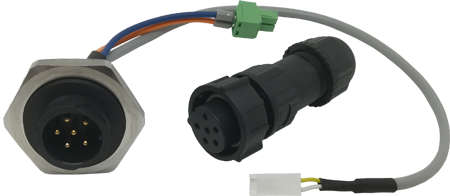
This kit is basically compose by 2 separated sections as explained below
Section A
to be installed on the gateway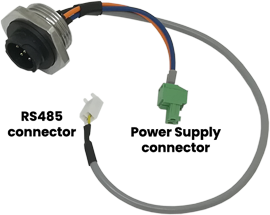
Section B
for waterproof wires connection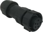
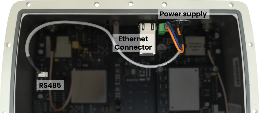
Section A Setup
Section A must be screwed inside the gateway case, on the first available slot from the right side of the gateway. On our gateways this slot is usually closed by a black cap. In order to do this, the first thing you need to do is to open your gateway and have access to the board. Then, connect the Section A like in the picture below
Note: if you will not plug any cable through the Ethernet cap, remember to switch it with the black cap you’ve just removed to keep your device waterproof (as Ethernet cap has a hole right in the middle of it)
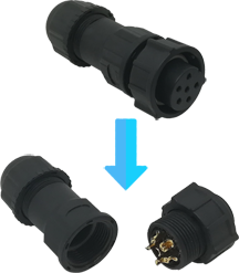
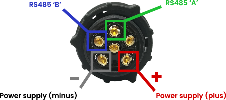
Section B Setup
Section B is the external waterproof part of the product. In order to connect wires, you need first to open the connector by unscrewing the middle section of it. It will appear like in the images below. Then you need to follow the wire-scheme as explained in the picture. Please be careful with the cables position. We suggest to place the “empty spot” at the bottom as reference marker